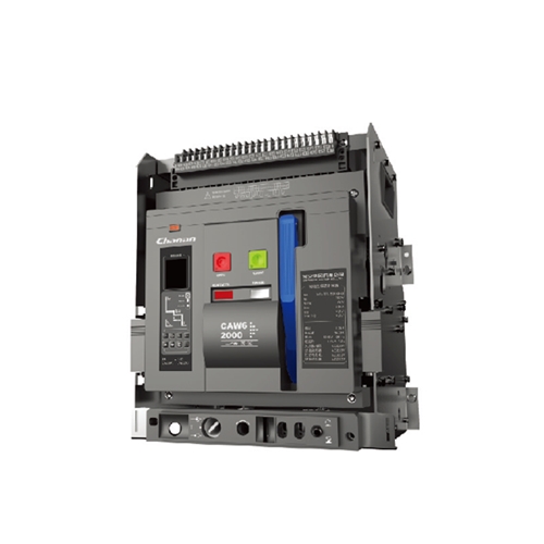
CAW6 ACB Intelligent Universal Circuit Breaker
Scope Of Application
CAW6 series intelligent universal circuit breaker (hereinafter referred to as circuit breaker) is suitable for AC 50Hz, rated voltage 400V, 690V, rated current 630 ~ 6300A.It is mainly used in distribution networks to distribute electrical energy and protect circuits and power equipment from overload, under-voltage, short circuit, single-phase ground faults. The circuit breaker has a variety of intelligent protection functions, which can achieve selective protection and precise action. Its technology can reach the advanced level of similar international products, and it is equipped with a communication interface, which can carry out“ four remote” to meet the control center and requirements for automated systems. Avoid unnecessary power outages and improve power supply reliability.
This series of products complies with IEC60947-2, GB / T14048.2 standards.
Model Meaning

Normal Working Condition
1. The ambient air temperature is -5℃~+40℃, and the average temperature of 24 hours does not exceed +35℃.
2. The altitude of the installation site does not exceed 2000m
3. When the maximum temperature of the installation site is +40℃, the relative humidity of the air shall not exceed 50%, and higher relative humidity can be allowed under lower temperature; the average maximum relative humidity of the wettest month is 90%, and the average minimum temperature of the month is +25℃, taking into account the condensation on the product surface due to temperature change
4. The pollution degree is level 3
5. The installation category of the main circuit of the circuit breaker, the under-voltage controller coil and the primary coil of the power transformer is IV, and the installation category of the other auxiliary circuits and control circuits is III
6. The vertical inclination of the circuit breaker installation does not exceed 5
7. The circuit breaker is installed in the cabinet, protection level is IP40; if add door frame,the protection level can reach IP54
Classification
1. The circuit breaker is divided into three poles and four poles according to the number of poles.
2. The rated current of the circuit breaker is divided into 1600A, 2000A, 3200A, 4000A, 5000A(capacity increased to 6300A).
3. Circuit breakers are divided according to purposes: power distribution, motor protection, generator protection.
4. According to operation mode:
◇Motor operation;
◇Manual operation (for overhaul and maintenance).
5. According to installation mode:
◇Fix type: horizontal connection, if add vertical bus, the cost of vertical bus will be
calculated separately;
◇draw-out type: horizontal connection, if add vertical bus, the cost of vertical bus will be calculated separately.
6. According to the type of tripping release:
Intelligent over current tripping release, Under-voltage instantaneous (or delay) release
and Shunt release
7. According to the type of intelligent controller:
◇M type (general intelligent type);
◇H type (communication intelligent type).
Main Technical Parameters
1. The rated voltage and rated current of circuit breaker
| Rated current of frame level Inm(A) | Poles numbers | Rated frequency(Hz) | Rated insulated voltage Ui(V) | Rated working voltage Ue(V) | Rated current In(A) | N pole rated current |
| 1600 | 34 | 50 | 1000 | 400、690 | 200、400、630、800、1000、1250、1600 | 50%In100%In |
| 2000 | 400、630、800、1000、1250、1600、2000 | |||||
| 3200 | 2000、2500、2900、3200 | |||||
| 4000 | 3200、3600、4000 | |||||
| 5000 | 400、5000、6300(Capacity increase) |
2. The rated short-circuit breaking capacity of the circuit breaker and the withstand current during short circuit (the arcing distance of the circuit breaker is“ zero”)
| Rated current of frame level In(A) | 1600/1600G | 2000/2000G | 3200 | 4000 | 5000 | |
| Rated ultimated short circuit breaking capacity Icu(kA) | 400V | 55/65 | 65/80 | 100 | 100 | 120 |
| 690V | 35/50 | 50 | 65 | 85 | 75 | |
| Rated short circuit breaking capacity Ics(kA) | 400V | 55/65 | 40/50 | 65 | 100 | 100 |
| 690V | 35/50 | 40 | 50 | 85 | 75 | |
| Rated short circuit making capacity Icm(kA)(Peak)/cosφ | 400V | 110/143 | 176/0.2 | 220/0.2 | 264 | 264/0.2 |
| 690V | 73.5/105 | 105/0.25 | 143/0.2 | 165 | 187/0.2 | |
| Rated short time withstand current Icw(1s) | 400V | 42/50 | 40/50 | 65 | 100 | 85/100(MCR) |
| 690V | 35/42 | 40 | 50 | 85 | 65/75(MCR) |
3. Operation performance of circuit breaker
| Rated current of frame level Inm(A) | 1600(G) | 2000(G) | 3200 | 4000 | 5000 | Operating cycles per hour | |
| Electrical life | AC690V | 1000 | 500 | 500 | 500 | 500 | 20 |
| AC400V | 1000 | 500 | 500 | 500 | 500 | 20 | |
| Mechanical life | Maintenance free | 2500 | 2500 | 2500 | 2000 | 2000 | 20 |
| With maintenance | 5000 | 10000 | 10000 | 8000 | 8000 | 20 | |
Note:
(1) During each power-on operation cycle, the maximum time for circuit breaker to keep on is 2s
(2) Each operation cycle includes: closing operation followed by opening operation(mechanical life),or connecting operation followed by breaking operation (electrical life)
4. Operating voltage and required power of circuit breaker shunt release, under-voltage release, operating mechanism, intelligent controller for energy release electromagnet

Note:
The reliable operating voltage range of shunt release is 70%~110%, and the release electromagne and operating mechanism are 85%~110%.
5. Performance of circuit breaker under-voltage release
| category | Under-voltage delay release | Under-voltage instantaneous release | |
| Tripping time | Delay 1、3、5、10、20s | Instantaneous | |
| Tripping voltage value | (37~70)%Ue | Can make the circuit breaker open | |
| ≤35%Ue | Circuit breaker cannot be closed | ||
| 80%Ue~110%Ue | Circuit breaker can be closed reliably | ||
| The return time is≥95% | Circuit breaker does not open | ||
Note:
The accuracy of the delay time of the under-voltage delay release is ±10%. When the voltage recovers to 85% Ue or above within 1/2 delay time, the circuit breaker will not be disconnected
6. Auxiliary contacts
◇Auxiliary contact form: four sets of change-over switches (default)
◇The rated working voltage of auxiliary contact of the circuit breaker, The rated control power is shown in Table 6.
| Use category | Power supply type | Conventional heating current Ith(A) | Rated insulated voltage Ui(V) | Rated working voltage Ue(V) | Rated control power Pe |
| AC-15 | AC | 10 | 400 | 400、230 | 300VA |
| AC-13 | DC | 200、110 | 60W |
7. Circuit breaker power consumption (ambient temperature +40℃)
| Current | 1600(G) | 2000(G) | 3200 | 4000 | 5000 | ||||
| Pole | 3 | 4 | 3 | 4 | 3 | 4 | 3 | 4 | 3 |
| Power consumption | 300VA | 400VA | 360VA | 420VA | 900VA | 1200VA | 1225VA | 1240VA | 1225VA |
8. Protection performance of intelligent controller
The intelligent controller has overcurrent protection features such as overload long delay inverse time limit, short circuit short delay inverse time limit, short circuit short delay time limit,short circuit instantaneous protection, etc. It also has single-phase grounding and leakage protection, load monitoring and other characteristics.
The protection current and time parameters of overcurrent protection feature are generally set by manufacturer according to user’s order requirements. The neutral line overcurrent protection of four-pole circuit breaker, the time parameter automatically tracks the phase line setting value in proportion. The proportional number is selected by user, that is, the N-pole rated current IN is 50%ln or 100%ln. If the user doesn’t have special requirements when ordering, then configure and adjust according to Table 8.
◇If user doesn’t have special requirements when ordering, the factory setting value of the intelligent trip controller is configured according to the following table:
| Overload long delay | Current setting value Ir1 | In | Delay time setting value t1 | 15S | |
| Short circuit short delay | Current setting value Ir2 | 6Ir1 | Delay time setting value t2 | 0.2S | |
| Short-circuit instantaneous current setting value Ir3 | 12In(In:2000A)、10In(In:2000A) | ||||
| Grounding fault | Current setting value Ir4 | CAW6-1600(G) | CAW6-2000(G) | CAW6-3200(4000) | CAW6-5000 |
| 0.8In or 1200A(Choose the small one) | 0.8In or 1200A(Choose the small one) | 0.6In or 1600A(Choose the small one) | 2000A | ||
| Delay time setting value t4 | OFF | ||||
| Load monitoring | Monitor current Ic1 | In | |||
| Monitor current Ic2 | In | ||||
Functional Characteristics Of Different Types Of Intelligent Controllers
M type: In addition to the four section protection features of overload long time delay, short circuit short time delay, instantaneous and earth leakage, it also has fault status indication, fault record, test function, ammeter display, voltmeter display, various alarm signal output, etc It has a wide range of protection characteristic area values and complete auxiliary functions. It is a multi-functional type and can be applied to most industrial applications with high requirements.
H type: It can have all the functions of M type. At the same time, this kind of controller can realize the“ four remote” functions of telemetry, remote adjustment, remote control and remote signaling through the network card or interface converter. It is suitable for the network system and can be centrally monitored and controlled by the upper computer.
1. Ammeter function
The current of the main circuit can be displayed on the display screen. When the selection key is pressed, the current of the phase in which the indicator lamp is located or the maximum phase current will be displayed. If the selection key is pressed again, the current of the other phase will be displayed.
2. Self-diagnosis function
◇The trip unit has ◇ the function of local fault diagnosis. When the computer breaks down, it can send out an error“ E” display or alarm, and restart the computer at the same time,the user also can disconnect the circuit breaker when needed
◇When the local ambient temperature reaches to 80℃ or the temperature in the cabinet exceeds 80℃ due to the heat of the contact, an alarm can be issued and the circuit breaker can be opened at a small current (when required by the user)
3. Setting function
Press the long delay, short delay, instantaneous, grounding setting function keys and +, – key to set the required current and delay time arbitrarily according to user requirements,and press the storage key after the required current or delay time is reached. For details,see the chapter on installation, use and maintenance. The setting of the trip unit can immediately stop executing this function when an overcurrent fault occurs.
4. Testing function
Press the setting key to make the set value current to long delay, short delay,instantaneous state, indicator shell and +、- key, select the required current value, and then press the testing key to carry out the test of release. There are two types of testing keys;one is non-tripping testing key, and the other one is tripping testing key. For details, see the tripping device test in the chapter of Installation, Use and Maintenance. The former testing function can be performed when the circuit breaker is connected to the power grid.
When an overcurrent occurs in the network, the testing function can be interrupted and the overcurrent protection can be performed.
5. Load monitoring function
Set two setting values, Ic1 setting range (0.2~1) In, Ic2 setting range (0.2~1) In, Ic1 delay characteristic is inverse time limit characteristic, its delay setting value is 1/2 of long delay setting value. There are two kinds of delay characteristics of Ic2: the first kind is the inverse time limit characteristic, the time setting value is 1/4 of the long delay setting value; the second kind is the time limit characteristic, the delay time is 60s. The former is used to cut off the least important load of the lower stage when the current is close to the overload setting value, the latter is used to cut off the unimportant load of the lower stage when the current exceeds the value of Ic1, then current drops to make the main circuits and important load circuits remain powered. When the current drops to Ic2, a command is issued after a delay, and the circuit that has been cut off by the lower stage is turned on again to restore the power supply of the entire system, and the load monitoring feature.
6. Display function of the tripping unit
The tripping unit can display its operating current (ie ammeter function) during operation,display the section specified by its protection characteristics when a fault occurs, and lock the fault display and fault current after breaking the circuit, and display the current, time and section category of the setting section at the setting time. If it is a delayed action, the indicator light flashes during the action, and the indicator light changes from flashing to constant light after the circuit breaker is disconnected.
7.MCR on-off and analog tripping protection
The controller can be equipped with MCR on-off and analog tripping protection according to the user’s needs. The two modes both are instantaneous actions. The fault current signal sends action instructions directly through the hardware comparison circuit. The setting current values of the two actions are different. The setting value of the analog tripping is high, which is generally the maximum value of the instantaneous protection domain value of the controller (50ka75ka/100kA), The controller works all the time and is generally used as a backup. However, the setting value of MCR is low, generally 10kA. This function only works when the controller power on, it does not work during normal closed operation. The user can require special setting value with accuracy of ±20%.
The Mechanical Interlocking
The interlocking mechanism can interlock two or three circuit breakers for multi-channel power supply system. The mechanical interlocking device is installed on the right board of the circuit breaker. When it is installed vertically, the circuit breaker is interlocked with connecting rod; when it is installed horizontally or vertically, the circuit breaker is interlocked with steel cable, and the interlocking device is installed by the user. See Fig. 1 and Fig. 2 for the interlocking schematic diagram.
◇ Connecting rod interlocking three vertically installed circuit breakers

◇ Steel cable interlock two circuit breakers installed horizontally

Shape And Installation Dimensions
◇ CAW6-1600(200-1600A Fixed type)
