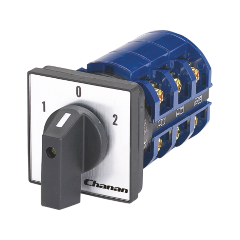
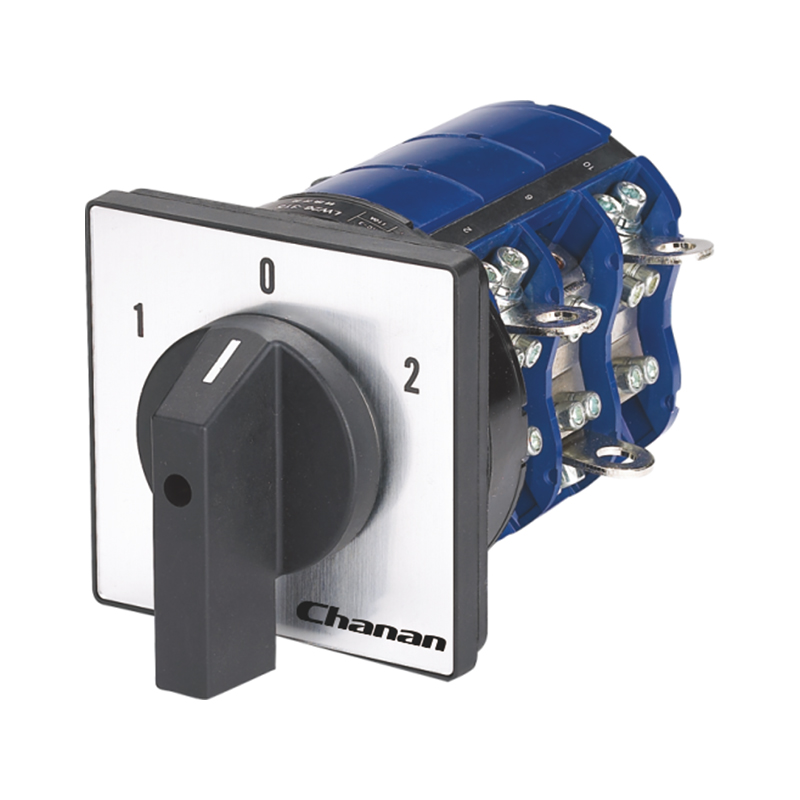
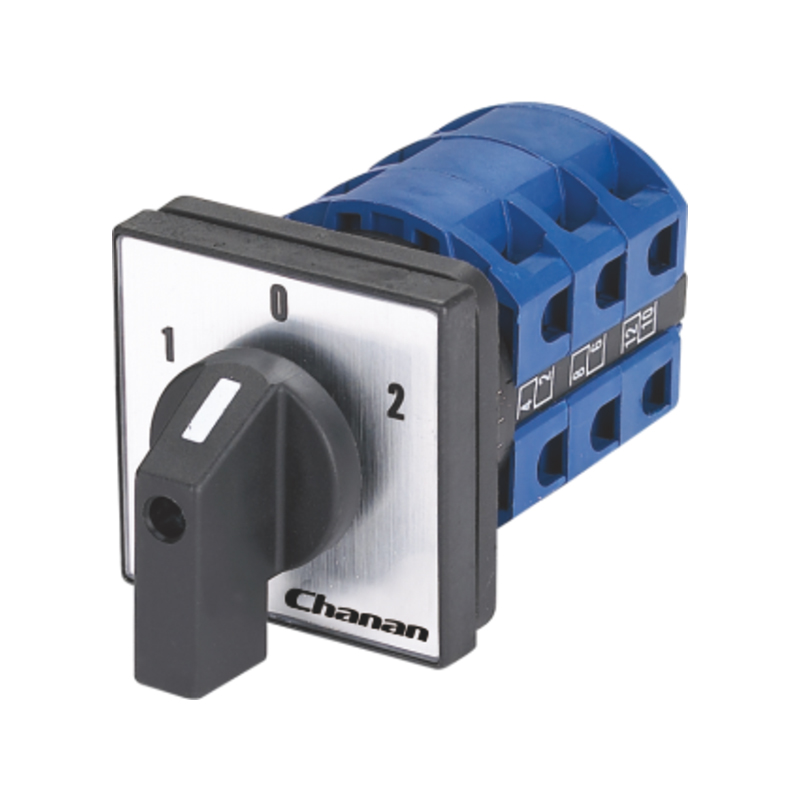
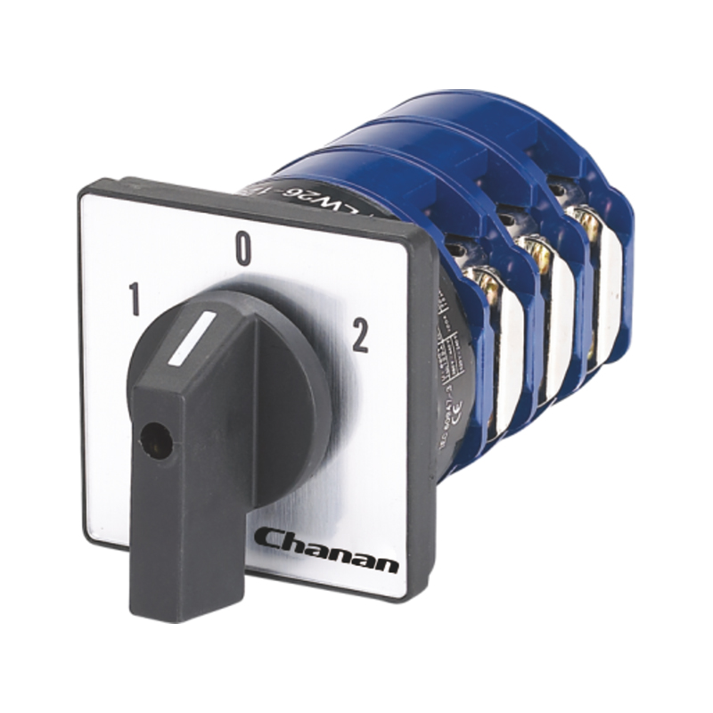
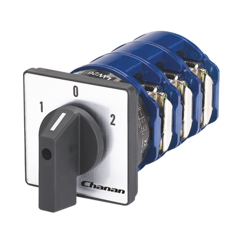
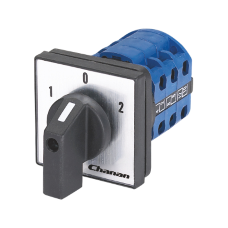
LW26 Rotary Changeover Switch

Introduction
The LW26 sereies rotary switch mainly applies to 440V and below,AC 50Hz or 240V and below DC circuits. For breaking and closing, change-over of circuits under unfrequently manual operation. And the typical application are: control switch of 3 phase motors, control switch of switch gear, control switch of instruments,and change-over switch of machinery and welding machine.
The series comply with the IEC 60947-3,IEC 60947-5-1.
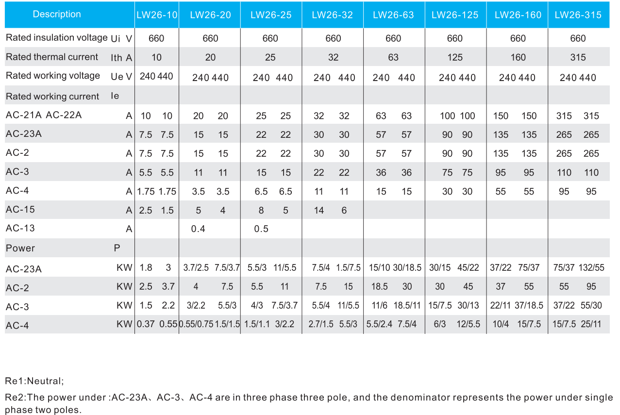
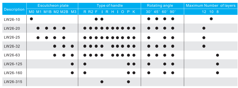
The LW26 series have 8 current ratings:10A,20A, 25A,32A,63A, 125A,160A and 315A.
The LW26 series rotary switch were designed for multiple functions, wide variety of applications.
The LW26-10,LW26-20,LW26-25 ,and LW26-32F have finger protection terminals.
Both of them are applicable in circuits when an physical control is required.
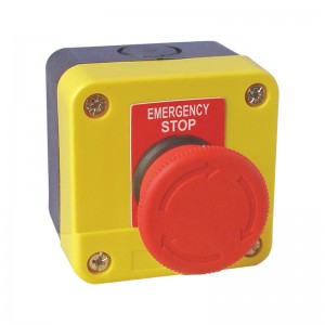
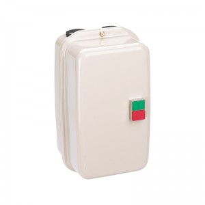
We can equip protective box for 20A,25A,32A and 63A. .
Working conditions
■ Ambient temperature do not exceed 40C, and the average temperature, measured over a
period of 24 hours, do not exceed 35C .
■ Ambient temperature should not be below -25C.
■ Should Not be installed over 2000m above sea level.
■ The humidity should not exceed 50% when the ambient temperature is 40C and higher humidity is allowed for lower temperature.
Installation conditions
■ A clean environments is required.
■ Please follow our manual
Classified by utilization
■ Change-over switch;
■ Motor switch;
■ Control switch.
Classified by operation
■Limied movement;
■Spring return;
■Limited movement with spring return.
Classified by contact system
■ Switches with limited movement could have 12 layers in maximum
■ (for 32 A and below ). And for 63 A and above could have 8 layers in maximum;
■ Switches with spring return could have 3 layers in maximum;
■ Motor switches could have 6 layers in maximum.
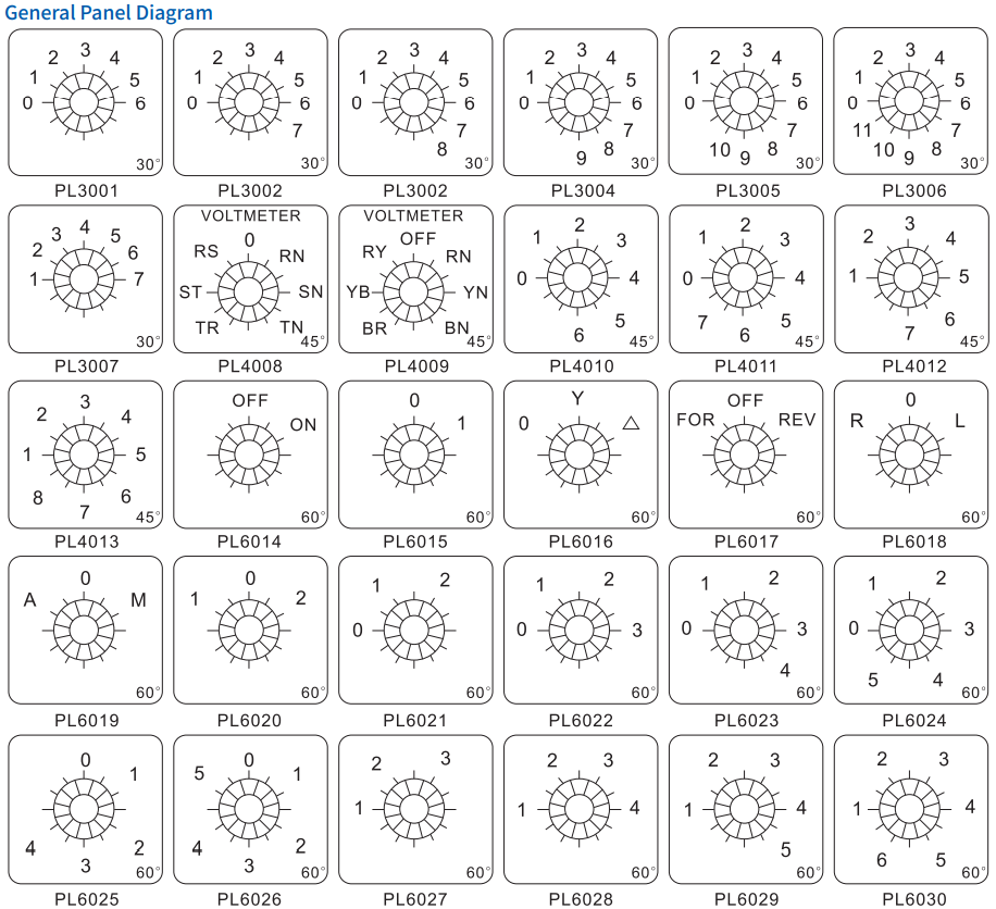
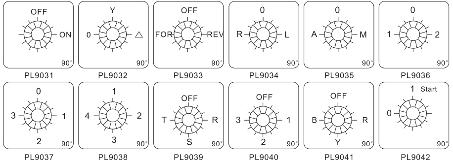
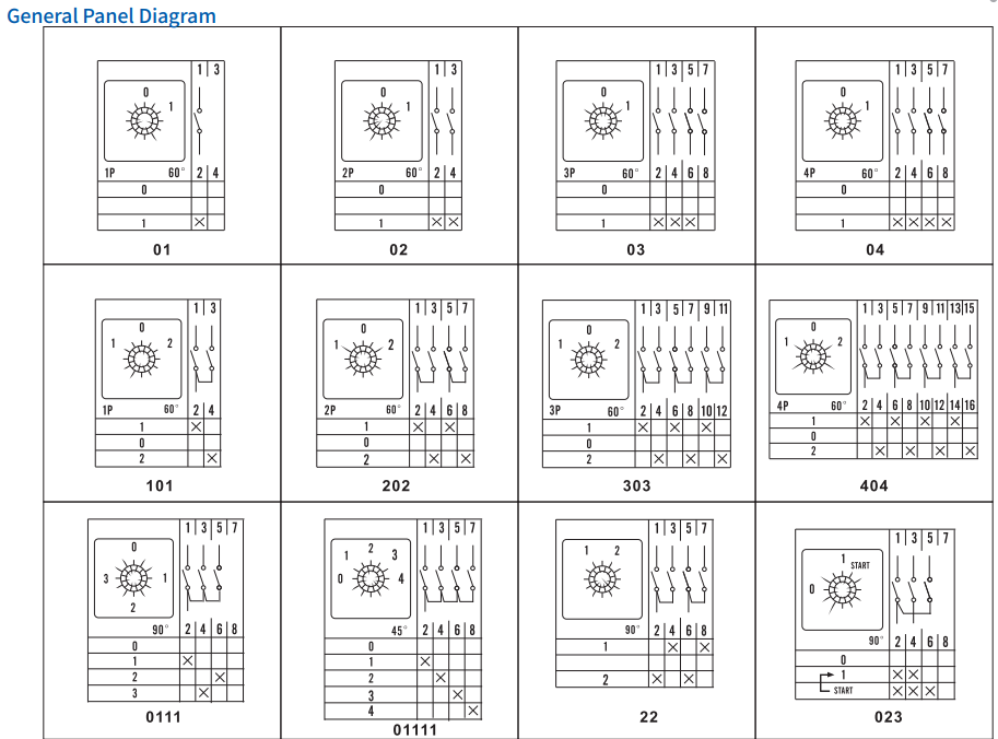
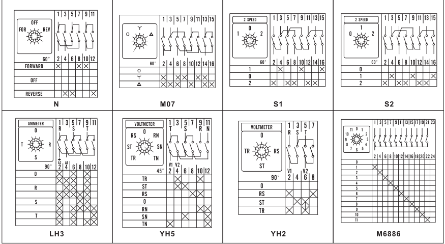
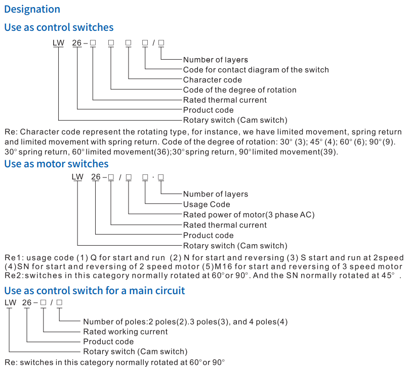
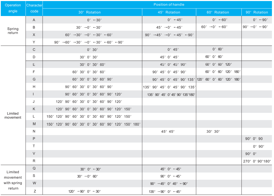
Diagram for the operation and position of handle
Technical parameters